What proper gate design is important?
The gate serves as the entrance to the
mould cavity and should be designed to permit the
injection mold to fill easily. It is very important to follow below gate considerations while picking gate location at the early stage of
plastic mould design.
- Gates should not be placed where part-bonding or impact will take place in use. The gate area will usually have higher residual stresses than the rest of the part due to the packing that takes place. Therefore, it will be weaker than the rest of the part.
- Position the gate to minimize trimming problems. Scissor-type gate cutters, kept sharp, will work smoothly and leave no “blemish” marks.
- If possible, gate into the thickest section to avoid incomplete fill or sink marks. This will also minimize flow marks and distortion associated with setting into a thick section from a thin one.
- Position the gate so that venting can be provided opposite it, at the parting line or an ejector pin.
- End gate parts where possible as side gating produces stresses due to the final packing necessary to remove sinks.
Improper gating can cause surface defects and excessive stress. If the gate is too small, high temperatures and pressures will be needed to fill the mold and may cause warpage and flow marks. If the gate is too large, the resin will jet into the cavity, entrap air and the part will have surface sinks.
Gate type
A variety of gate designs and locations are shown below:
- Sprue Gates leave large trim marks and are slow to cool. They may allow jetting and overpacking but make it easy to fill a part, especially if thick sections are involved, and are inexpensive to machine.
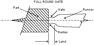
- Full Round Gates may cause flow patterns or surface defects from jetting, or warpage due to the relaxation of packing stresses. Sharp edges entering the cavity should be flared. The minimum diameter is about 1.5mm (0.060″) and land should be as short as possible, and not less than 1.0mm (0.040″). These gates trim clearly and are inexpensive. (Figure 1)
Figure 1
- Pinpoint Gates can cause problems. The fault often lies not so much with the gate as with the approach to the gate which is often long, thin, and tapered. (Figure 2) The gate land length appears to be very short, but because the gate is choked off when the resin freezes, the effective land length diameter may vary.
Figure 2

Figure 3 shows another approach to the gate which helps to keep the gate hot and open. The land length will change less during injection, and a higher effective cavity pressure will result during fill.
Figure 3

- Tunnel Gates may exhibit some of the same warpage and jetting problems as full round gates. Too small an included angle may result in excessively high pressure drops. They can be used most effectively if the length of the tapered section and the land length are minimized, and the part has a short flow distance (a length to thickness ratio ~50).
Gates of 1 .5mm (0.060″) diameter, minimum can be used. Knockout pins for the part and the runner should be located near the gate. (Figure 4)
Figure 4

- Rectangular Gates have some of the same disadvantages as round gates, but the depth and width can be changed independently to increase area (reduce pressure drop) without increasing gate freeze off time. A typical starting dimension would be 1.3mm (0.050″) thick by 3.Omm (0.125″) wide with 1.3mm (0.050″) minimum land. (Figure 5)
Figure 5

- Fan Gates are a type of rectangular gate. However, because of the shape in transition and decreasing thickness from runner to gate, the fan gate reduces stresses as the melt enters the cavity and so improves part toughness. This type of gate can be useful for parts with thick sections. (Figure 6) A typical starting dimension would be 6.3mm x 1.3mm (0.25″ wide by 0.050″ thick) with 1.3mm (0.050″) minimum land.
Figure 6

- Tab Gates are not really gates, but tabs or extensions of the part that the gate enters. The tab deflects the flow and is then cut from the part to remove any highly stressed areas. The gate into the tab should be flared to avoid jetting at high fill speeds. Tabs can be trimmed cleanly at the machine. (Figure 7)
Figure 7

- Ring and Diaphragm Gates are thin, continuous gates designed to fill tubular parts uniformly. The diaphragm gate has the advantage of low pressure drops and is often capable of faster cycles. Ring gates are less satisfactory because if faster filling at the runner inlet side of the part leads to differential packing, it could produce warping. (Figure 8)
Figure 8

- Flash Gates are often used for thin, flat parts. A runner parallel to the gate is suggested for distributing the resin smoothly along the part and keeping the gate open longer to prevent premature freezeoff. (Figure 9)
Figure 9

Thick walled parts, sections 6.4mm (0.25″), will need gates of half the part thickness or greater, or in extreme cases equal to the section thickness. Cycle times will be correspondingly long.
In summery, a mould cavity can have more than one gate. Gates should be small enough to ensure easy separation of the runner and the part but large enough to prevent early freeze-off of plastic flow, which can adversely affect the consistency of plastic part dimensions.


 Español