

 Español
Second ejection mechanism:
Add an extra set of ejector plate. The first set of ejector plate that is attached to the A plate(referred as Ejector Assembly A) is to complete the first stage of ejection while the ejector plate attached to B plate (referred as Ejector Assembly B) is to complete the second stage of ejection as shown in Figure1.
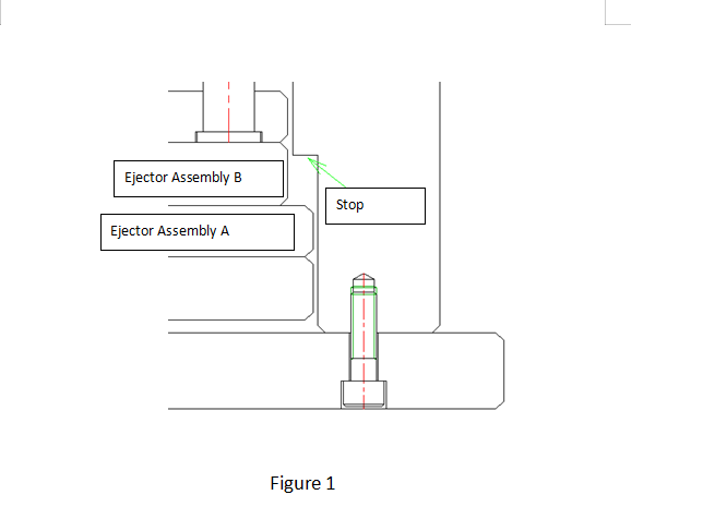
Figure 1
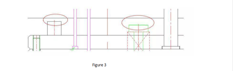
Add series of springs or nylon plugs to make sure that both ejector assembly A and B are attached together as a unit. After the tool opens, both ejector assemblies A and B move forward together as a single un il assembly A is forced to stop by the cavity support plate above it. As the ejection stroke continues, the springs compress, allowing assembly B to continue forward until they in turn hit the stops
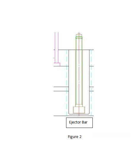
Calculate the stroke of both ejections depending on specific part design. Total stroke should be longer than that of first ejector. Limit screws could not be higher than limit stops as shown in Figure 3
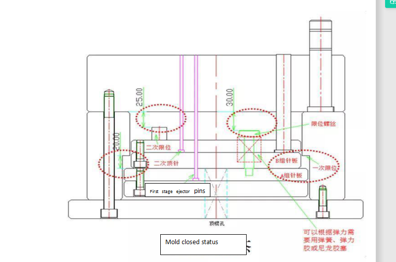
 Phase1 Mold tool closed status:
In this phase, Figure 4 shows that both ejector plates are closed tightly to the fixing plate under springs. All mechanisms are in the status of “ closed” as shown in Figure 4.
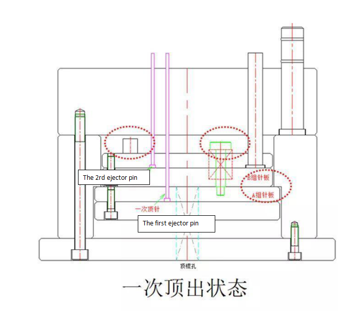
Phase2 ejection :
In phase 2 a hydraulic ejector pushes forward both ejector assemblies A and B together as a single unit to free the outer wall section so that the moulding may be able to deflect. Once this has occurred, the first-stage ejection assembly A hits a fixed stop and cannot move any further forward to complete phase. As show in Figure 5
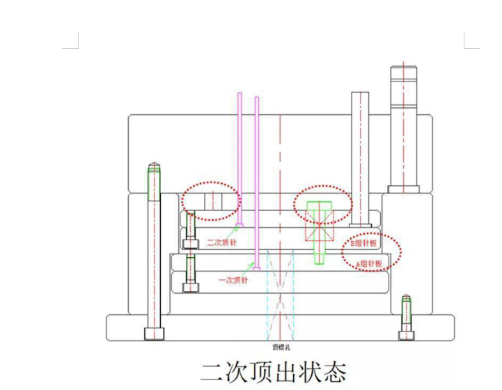
Phase 3:
The second-stage ejector assembly B moves further forward, leaving the first stage behind, thus completely clearing the moulding from the cavity.
As shown in Figure 6
The key to the operation of this type of double ejection design is the module that connects the two ejector plate assemblies together. A spring-loaded system ensures that the two systems move forward together as a single unit to complete the first stage. The lower assembly then hits a mechanical stop, the collet disengages, and the upper assembly continues forward, completing the second stage.
HS Mold built our reputation on injection molds. So our engineering team ensures a professional and efficient process from concept to realization. We provide solution-oriented communication throughout each project, designing and manufacturing molds for customers around the world.